Comparator Distortion
I had an idea for a module that I’m pretty sure hasn’t been made yet. The idea was this: what if you used a whole bunch of comparators to convert an input signal (audio or cv) into a discrete stepped output? And what if you could control the number of steps and distance between them continuously with CV?
It would be similar to a sample & hold, but without the need for a clock. The output would be based solely on the input voltage. What would that sound like? I decided to build one and find out.
This one took over a year of continuous development, testing, redesign, giving up, starting over… but in the end I got it working exactly as I envisioned when I set out. Let’s dive in, starting at the most fundamental level.
Comparators
A comparator is one of the simplest circuits around. There are dedicated comparator ICs, but op amps in open loop mode can also function as a comparator.
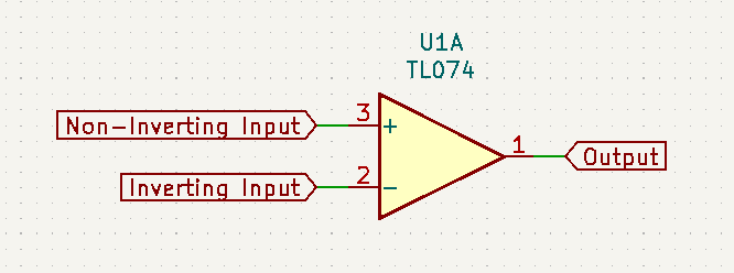
There are two inputs and one output. If the voltage at the non-inverting input is higher than the voltage at the inverting input, the output will be a positive voltage. If the inverting input is a higher voltage than the non-inverting input, the output will be a negative voltage. The output voltage is usually the same as the IC’s supply, so in eurorack it’s always +12V or -12V.
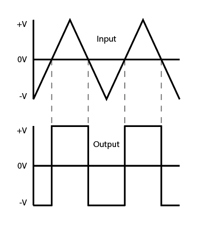
Comparators are often set up with the inverting input tied to a reference voltage (fixed or variable) for a single signal to be compared against. In this way, any input can be converted to a series of pulses.

For this module, I want to use several comparators with different reference voltages at their inverting inputs, and average the outputs in order to create a stepped wave.

As you can see, this only works on the positive half of the wave; in order to complete this idea, we can simply invert the input and run that through an identical series of comparators in parallel to the uninverted signal.
To put this all together, we will need some comparators, some inverting amplifiers, and a voltage divider (to get the reference voltages). Here is how the circuit looks using comparators at 1V intervals over a 5V range:
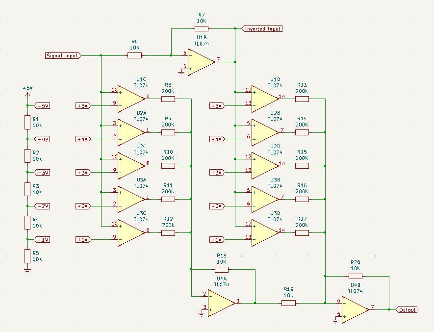
A couple of notes about this circuit:
Five resistors of equal value form a voltage divider between 5V and 0V - this gives 1V increments over 5V.
In theory, each op-amp’s output should be either +12V or -12V. However in the real world the values are closer to +/- 10.8V. For my calculations I will round that to +/- 10V just to make the math simpler, it’s close enough.
Resistors R8 - R17 are all 200K and the mix feedback resistors are 10K - this scales down each op-amp’s output to +/- 0.5V, a swing of 1V each.
When I first put this together, I wasn’t sure if I would need to use rectifiers or do any complicated arithmetic to cancel out the outputs from negative voltage inputs. I decided to built it in the simplest form possible first, and make changes as needed. It turned out the negative voltages cancel out by themselves!
If we test this with a 10Vpp triangle wave, here is what the result would look like:

Mostly looks good, but there are a couple of issues: since the triangle never exceeds 5V, the uppermost comparator is never triggered; also it looks a little funky around 0V because there is a two volt range from -1V to +1V where the circuit outputs 0V.
We can fix both of these by tweaking the reference voltages. The way it is now, an input between 1 and 2 volts will output 1V, an input between 2 and 3 volts will output 2V, etc. If we offset the reference voltages down by 1/2 V, then an input of 0.5 to 1.5 volts will output 1V, 1.5 to 2.5 will output 2V, and so on. Basically the circuit will round any input to the nearest whole number voltage. So instead of using 1, 2, 3, 4, and 5 volts, we should use 0.5, 1.5, 2.5, 3.5, and 4.5 volts. That will solve the issues and clean up the output.


Much better! The core of the circuit works. For the final module, I will double the number of comparators in order to get finer resolution, but the principle is the same.
Adding CV Control
Now the next step is to add a parameter we can tweak - as is, the circuit is just one input and one output with no controls.
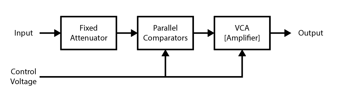
My idea here was to add some VCAs. The input could be attenuated before hitting the comparators, and then the output would be amplified back up to the original amplitude.


By doing this, the input passes through fewer comparators and the output is lower resolution, more distorted. Attenuating the input in this way also allows us to change the resolution fluidly, so you can sweep the distortion with a knob turn or CV.
In practice though, this proved very hard to achieve. The hard part is setting up the VCAs to balance each other out and return an output at the same amplitude as the input. We need one CV to move both VCAs in opposite directions - and for that, we’d need a way to convert an input CV of X volts to a reciprocal value of 1/X volts. Turns out there’s not an easy way to do that.
There are dedicated VCA ICs that can be set up for a linear or logarithmic response, so I decided to test some out. I thought maybe I could do some simple inverting/offsetting/attenuating the CV, run one VCA in linear and another in log and maybe it would work? Unfortunately it didn’t. I tried with the SSI 2164 and the AS 3360 and neither could pull it off.
After that didn’t pan out, I tried a different approach. I though about using envelope followers on the input and output, and setting up a kind of negative feedback loop to force the output to an amplitude where it’s envelope is the same as the input’s envelope.

For the VCAs, I used the SSI 2164 configured as shown in the datasheet. I decided on that IC mostly because I already use it in the Lunar Delay and a few other projects I’m working on, so it’s more convenient to keep in stock

For the envelope followers, I used one of the more simple setups. Just a precision rectifier followed by a large capacitor to ground and large resistor to ground. I made sure to set up the input EF with a positive rectified envelope and the output EF with a negative rectified envelope so I could use a simple summing op amp to get the difference. That difference in voltage is used to adjust the level of the output, so if the output is higher amplitude than the input, the differential voltage goes down which in turn adjusts the output VCA to be lower. And if the output is lower amplitude than the input, the differential voltage goes up which boosts the output VCA. Everything stabilizes when the input and output are at the same level.

And surprisingly, this pretty much worked! There are a few downsides, though.
Envelope followers are inherently kind of shitty. You have to choose a slew rate that smooths out the audio rate frequencies while still responding quickly to changes in amplitude. You can’t get either one to be perfect, and trying to balance them means compromising on both.
As a result, there is some ripple in the EF signals that gets incorporated in the output. It’s not a bad sound necessarily but it isn’t how I envisioned this module.
This only works with audio signals, the module can’t be used to generate stepped CV.
So overall, it works but there’s a lot of compromises. I decided to add a switch to bypass this whole section so CV can still be processed into stepped CV - but in that mode there’s no output amplifying VCA.
I also wanted to find a way to get PWM kinda effects from this module. My first idea was to have two CV inputs, one for big sweeps and one for smaller, more subtle changes. Unfortunately the smaller one didn’t sound like PWM and ended up not being too useful.
But hey, the module is working! I put it in my rack and played with it for a while, but in the back of my mind I was always wondering if it could be improved…
The Improvements
Several months later, I was thinking about this one again from the beginning. If you attenuate the input, then the output will be attenuated also and need to be amplified - that’s the core problem that all the other issues stem from. Could there be another approach?
Then I considered that comparators have two inputs, one signal and one reference voltage. What if, instead of attenuating the signal, you leave the signal alone and amplify the reference voltage? If the reference voltage goes up… then the output would go DOWN… amplify the reference voltage and then amplify the output… you could amplify them by the same amount! The difference might cancel out and the output would be the same amplitude as the input! HOLY SHIT.

I breadboarded it and sure enough, it worked! Still needed a few more tweaks to finalize but now I know the idea is viable.
A new issue now is that I want to amplify the reference voltages, but they already range up to 5V. Going up to 12V would only give an amplification of 2.4x. To get around this, I will attenuate the input by a fixed amount and then amplify the output back up by that same amount. Since there is already a VCA at the end of the chain, I will simply scale up the gain of that VCA instead of adding a second amplifier.
I decided to attenuate the input to 10% of it’s original amplitude. Assuming a range of +/- 5V means it will now be +/- 0.5V. Then with ten comparators and ten reference voltages, with the uppermost reference voltage at 0.5V a +/- 5V input will trigger all 10 comparators. The reference voltages can be scaled up 10x to 5V and then a +/- 5V input will trigger only one comparator.
So we want the reference voltages (summed from a pot and CV input jack) to range from 0.5V to 5V. A wrinkle here is that lower voltage leads to higher resolution, so the pot needs to be wired backwards and patched CV should be subtracted instead of added. Doing it this way ensures that if the pot is swept from left to right (or if CV is increased), the reference voltages are decreased so that the output resolution is increased.
Also - after playing with the module for a while I found that adding DC offset to input audio generates some beautiful PWM-style effects. I decided to add a second input so that audio can be offset with an LFO or other modulation to make that kind of sound easier to achieve. So there is an audio input and a second input for offsetting audio. The second input can also be used to process CV and turn it into stepped CV at the output. I wasn’t sure the best way to label these, calling them Audio In and CV In would be confusing since the CV isn’t modulating anything. I decided to call them AC In and DC In, I felt that still describes their functions without being misleading.
So here is what the Input and CV processing looks like:
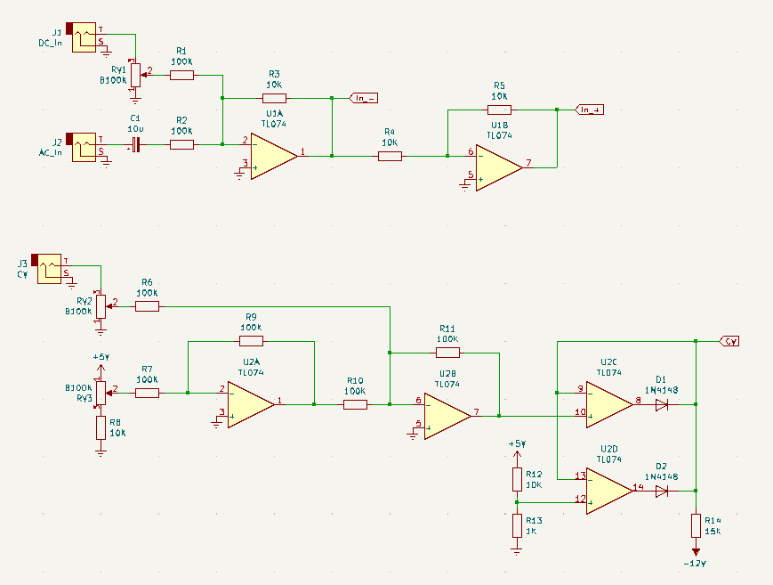
Note also the logical max around D1 and D2 - this is to prevent the reference voltages from being attenuated too much. There is a hard lower limit of 0.5V. There isn’t much change in behavior below that point, but if it gets to 0V then the module won’t work.
The node labelled “CV” goes to both the reference voltages and the output VCA’s control input.

This is a linear VCA copied straight from the datasheet.
Each cell of the 2164 has an exponential response, here U3A and U1C form a linear to exponential converter on the CV controlling U3B.
In the datasheet, R19 is 20K, and this provides unity gain; I increased the value 5x in order to boost the output back up to the same level as the input.
Final Thoughts
I really can’t state enough how satisfied I am that this is working. I spent a long time revising this circuit to get it functioning just the way I wanted and I can’t believe it all came together. Plus, in my opinion it sounds really good.
That said, there are still some things I might try to implement down the road. A wet/dry knob might be useful as this is an audio effect. I considered adding one but decided against it as there are already way too many components for a module with basically one parameter.
Another thought I had was to try making a similar module, but instead of op amp comparators base it around a bunch of copies of diode distortion circuits. So it would be similar overall, but with more of that creamy analog warmth (TM) in the sound. I’m not sure if that is even a viable idea but I’d like to test it out one day.